How to use
This page walks through the recommended workflow for processing one folder or a selected batch of folders with Quadrant Folding (QF), then describes secondary features and headless mode.
Workflow at a glance
Step 1 — Open an image or choose batch folders
Use File > Select an Image… (Ctrl+I) and pick any TIF/CBF/HDF5 file. QF loads the file, discovers all sibling images in that directory, and immediately processes the selected image with the default settings.
Once a folder is loaded, use the navigation arrows on the bottom strip to move through images:
< / > — previous / next image
<<< / >>> — previous / next HDF5 file (only for HDF5 input)
Process Current Folder — reprocess every image in the folder with the current settings
Process Current H5 File / Process All H5 Files — same for HDF5 frames
Choose Batch Folders — select and order multiple source folders for navigation, alignment review, and batch processing
Already-processed images are reloaded from the cache rather than reprocessed, so navigation is fast. To force reprocessing, click Process Current Folder or delete the qf_cache folder under the output directory.
Select multiple folders
Click Choose Batch Folders in the navigation area.
Use Choose Root Folder if the folder tree should start somewhere else, then check each folder to include. Folders without supported images are skipped when the dialog is accepted.
Review Selected order and use the up/down buttons to set the processing order.
Click OK. The button reports the selected folder count, the navigator immediately loads their images, and Process Current Folder changes to Process Batch Folder(s).
The alignment table includes all images from the selection and identifies their source in its Folder column. Choosing no folders restores the original single-folder image list and controls.
Step 2 — Choose an output directory
By default QF writes qf_results/, qf_cache/, and CSV files into the same folder as the input images. If the input directory is read-only, or you want to keep input and output separate, use File > Change Output Directory… before processing.
The output directory applies to:
qf_results/<name>_folded.tif— the folded imageqf_results/bg/<name>.bg.tif— the estimated background (when subtraction is on)summary.csv,summary2.csv,failedcases.txt— batch summariesqf_cache/— processing fingerprints used for fast reload
Step 3 — Set center and rotation on a reference image
Pick a clean, well-aligned frame as your reference. The right-hand Set Center and Set Rotation Angle panels contain everything needed.
Center tools
Button |
When to use |
|---|---|
Quick Center and Rotation Angle |
Click opposite reflection peaks; their midpoint sets the center and their connecting line sets the rotation. |
Set Center by Chords |
Select points along a strong ring; the center is fitted from the perpendicular bisectors of the resulting chords. |
Set Center by Perpendiculars |
Draw two perpendicular lines through pairs of symmetric reflections. |
Set Center by Calibration |
Use a calibrant ring or saved |
Set Center Manually |
Click a single pixel to use as the center. Fast but least accurate. |
Refine Center |
Improve the current estimate with registration, gradient, and local-search refinement; optionally save its refined rotation too. |
Apply Center |
Copy the current center to subsequent, previous, or all images. |
Restore Auto Center |
Discard the manual center and revert to auto-detection. |
Rotation tools
Button |
When to use |
|---|---|
Set Auto Orientation |
Open a dialog to pick the rotation-detection algorithm and whether to use Mode Orientation (use the most common angle across the folder). |
Set Angle Interactively |
Click two points to define the meridional axis. |
Set Angle Manually |
Type the angle in degrees. |
Refine Rotation |
Refine the current angle while keeping the current center fixed. |
Apply Rotation |
Copy the current angle to a chosen scope. |
Restore Auto Rotation |
Revert to auto-detected angle. |
For full details on all shared tools (Double Zoom, fingerprinting, calibration dialog), see Common Settings — Diffraction Center and Rotation.
Refinement starts from the current geometry, so first obtain a reasonable automatic, calibrated, or manual estimate. Refine Center may take a few minutes; select Also refine rotation only when both returned values should replace the current settings. A successful refinement shows the old and new values, stores the accepted result as manual geometry, and reprocesses the image once.
Once the reference image looks right, use Apply Center and Apply Rotation with Apply to all images to propagate the values. If batch folders are selected, this scope applies across the selected batch and each source folder receives its own saved manual geometry.
Optional intensity corrections
The Image Processing panel can apply geometry-dependent intensity corrections before QF transforms and averages the quadrants:
Solid Angle corrects the variation in solid angle across a flat detector.
Polarization applies the selected Unpolarized, Horizontal, or Vertical incident-beam model.
Both corrections require a positive sample-to-detector distance and pixel size from Calibration Settings. If this geometry is unavailable, QF leaves the image unchanged and reports that the requested correction was skipped. Changing either correction invalidates dependent cached results and reprocesses with the new setting.
Step 4 — Detect alignment across the loaded images
After propagating, most images will be correctly aligned, but some may have shifted center or rotation and need individual correction. Open Tools > Detect Image Alignment… (Ctrl+D) or click Detect Image Alignment… in the right panel.
The dialog shows one row per image with columns for:
Folder and Frame — source location and image name
Current Center and Center Mode — center captured from the saved manual/automatic geometry at the start of the current detection snapshot
Dist from Base — distance between the current center and the center of the selected base image
Auto Center and Auto-to-Current Difference — automatic estimate and its distance from the current center
Rotation and Rotation Mode — applied angle and its source
Rot Diff from Base, Auto Rotation, and Auto Rot Difference — axial angle differences, where orientations 180° apart are treated as equivalent
Size and Image Difference — pixel-difference between this image and the base
Fold Std (sum) and Fold Std (norm) — raw and exposure-normalized fold-symmetry scores (lower = more symmetric)
Run symmetry test on detection is enabled by default. Click Detect Centers & Rotations to capture a coherent snapshot of the latest saved geometry, refresh the table, and recompute automatic geometry, image differences, and symmetry results for every loaded image. Capturing one snapshot at the start prevents center or rotation edits made during a long detection pass from mixing old and new geometry in the same result set.
Checked thresholds highlight rows whose values exceed the selected limit:
Center Diff from Base threshold and Auto-Rot Diff threshold use the entered pixel/degree limits.
Image diff threshold, Symmetry std threshold, and Symmetry norm threshold default to the 80th percentile after detection.
Uncheck an individual threshold to disable only that highlighting rule.
Sort any column to surface outliers. For example, sort Auto-to-Current Difference to find automatic centers that disagree with the captured geometry, or Fold Std (norm) to compare symmetry across different exposures and image sizes.
The dialog is non-modal: leave it open and switch between it and the main window freely. Center and rotation changes made in the main window are saved immediately, but the table deliberately continues to show its current snapshot. Click Detect Centers & Rotations again to capture those changes and refresh the comparisons.
Step 5 — Fix individual misaligned images
For each outlier in the alignment table:
Click the row — the main window navigates to that image.
Adjust center / rotation using the Step 3 tools on the main window.
Click Detect Centers & Rotations again. The table captures the saved correction and recomputes its alignment and symmetry diagnostics.
Right-clicking a row offers:
Set Center and Rotation — switches focus to the main window with a hint dialog.
Set Global Base — promote this image as the reference for the
Dist from Basecolumns.Ignore — exclude this image from subsequent batch operations.
Repeat until all images are within an acceptable tolerance.
Step 6 — Inspect the result and switch display modes
Switch to the Results tab to see the folded, background-subtracted output. The display panel on the right has a Show dropdown that switches between several views without reprocessing:
Mode |
What it shows |
|---|---|
Subtracted |
Final result: average fold with background removed, mirrored to full 2D pattern. This is the default. |
Folded |
The plain average fold without background subtraction. |
Background (Non-param) |
The background image estimated by the non-parametric method. Useful for sanity-checking the subtraction. |
Background (Fit) |
The background image from the parametric (iterative 2D) fit. Appears only after the parametric fitting dialog has been opened. |
Evaluation Mask |
The composite mask used by the background optimizer (R-min/R-max annulus, equator band, peak/beam exclusions, layer lines). Appears only after Advanced Configuration for Non-parametric Background Subtraction has been opened. |
Synthetic Signal |
The synthetic Gaussian-blob grid added to the fold during optimizer scoring. Appears only after Advanced Configuration for Non-parametric Background Subtraction has been opened. |
Synthetic Mask |
The mask region of the synthetic data. Appears only after Advanced Configuration for Non-parametric Background Subtraction has been opened. |
The last three views are diagnostic aids for tuning the optimizer and stay hidden until you open Advanced Configuration for Non-parametric Background Subtraction; Background (Fit) stays hidden until you open the parametric fitting dialog. The dropdown lists only the views that apply to the work you have started.
Other Results-tab controls:
Rotate 90 degree — rotate the displayed result by 90° (also rotates the saved tif).
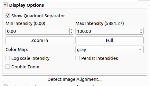
Show Quadrant Separator — draw the horizontal/vertical lines separating the four mirrored quadrants.
Persist intensity — keep the min/max intensity range across images.
Step 7 — Configure background subtraction (optional)
Background subtraction is not required for quadrant folding itself. If you only need the folded image (higher signal-to-noise, no diffuse background removed), leave the method as None and skip to Step 8. Use this step when you want to remove the diffuse muscle background before saving or downstream analysis.
The Background Subtraction group on the right panel is the central control. QF offers three approaches, from the most basic and hands-on to the most automated. For the full description of every method, parameter, and metric, see Background Subtraction.
Manual non-parametric subtraction
The most basic approach: you pick one method and set its parameters yourself. Expand Non-parametric Background Subtraction and in Subtraction Method choose one of the methods (2D Convexhull, Circularly-symmetric, White-top-hats, Roving Window, Smoothed-Gaussian, Smoothed-BoxCar, Average or None), and tune its parameters by hand. Then click Apply Selected Subtraction Settings. Use this when you already know which method suits your data. See Background Subtraction — Subtraction methods and parameters and Manual Setting.
Transition mode
When a single method does not work well across all radii, use two non-parametric methods and blend them: one for the inner region, one for the outer. Switch the right-panel Options dropdown to Manual Setting | Transition. Two method choices and parameter sets appear; configure each independently and set:
Transition radius — where the two backgrounds are blended (typical guideline: just outside the M3 meridional peak).
Transition delta — width of the linear blend region.
See How it works — Merge images for the algorithmic detail.
Automated (optimized) subtraction
Instead of choosing parameters by hand, let QF search for them. Switch the right-panel Options dropdown to Automated Processing. The quickest form is the blue Apply Default Optimization button: QF runs the automated optimizer on the current image using the default method set and writes the chosen method and parameters back to the Current Configuration display. This is the recommended first step on a new dataset. For finer control, open Advanced Configuration, and choose which methods to try, the step schedule, max iterations, and an early-stop loss threshold. See Background Subtraction — Automated Processing.
The Advanced Configuration dialog
The automated approach uses the Advanced Configuration (Background Subtraction Settings) dialog for the optimizer, evaluation masks and metrics, saved configurations, and batch launch. Its three-step layout is documented in full on the Optimization Settings page.
Parametric (iterative 2D) fitting
The parametric method models the diffuse background as an explicit 2D function — an equatorial-streak component plus a general background component — and subtracts it, rather than estimating it numerically. Expand the Parametric Background Fitting panel and open the Iterative 2D Background Fitting Dialog. Use it when the background should be removed from the whole pattern or when a smooth analytic background is preferable. It can be combined with a non-parametric method: after applying a parametric fit, enable Subtract fitted before non-parametric so a non-parametric method runs on top of the fitted residual. See Background Fitting for the full model and settings reference.
Step 8 — Process the folder or batch and collect output files
When the settings look right on representative images, click Process Current Folder or, for a multi-folder selection, Process Batch Folder(s). The same processing and background settings are used for the selected images, while manual center/rotation values and CSV managers remain associated with their source/output folders so results from different folders are not combined into one summary accidentally.
qf_results/
File |
Description |
|---|---|
|
The folded, background-subtracted result image (32-bit float TIFF). When Save Compressed Image is checked, written as |
|
One row per processed image. Key columns: |
|
Same data, transposed for easier spreadsheet analysis. |
|
Images that could not be processed automatically (no peaks, fitting failed, high error, or manually rejected). |
qf_results/bg/
Written when a background-subtraction method other than None is active.
File |
Description |
|---|---|
|
The estimated background image (32-bit float TIFF). |
|
|
|
Per-image raw and normalized evaluation metrics with their weights and running means. Written only when Save result metrics to csv is enabled. |
For the meaning of loss, bgSum, and symmetry, see How it works — Evaluate result.
Methods Reference
These six methods are available in the Background Subtraction dialog. The algorithms are described in detail in How it works — Search and apply background subtraction. Here is the parameter cheat-sheet:
Method |
Key parameters |
|---|---|
Circularly-symmetric |
Pixel range %, radial bin size, smoothing factor |
2D Convexhull |
R-min, angle bin (default 1°) |
Roving Window |
R-min, window size (X/Y), pixel range %, smoothing, tension |
White-top-hats |
Top-hat disk size |
Smoothed-Gaussian |
R-min, number of cycles, Gaussian FWHM |
Smoothed-BoxCar |
R-min, number of cycles, box car size (X/Y) |
In Transition mode each method has a separate outer-parameter set (suffix _out in the JSON).
Other features
Right-click — Ignore a quadrant
Right-click on any quadrant in the Original Image tab and choose Ignore This Quadrant. The selected quadrant is excluded from the averaging step (useful when one quadrant has a detector defect or shadow). Use Unignore This Quadrant to re-include it.
Save and load settings
QF automatically stores per-image center and rotation in each folder’s manual settings and stores accepted calibration separately in
calibration.info.File > Save Current Settings (
Ctrl+S) — write reusable processing settings toqfsettings.json, including background processing, optional intensity corrections, output compression, and ROI size only when Persist ROI size is enabled. Per-image center/rotation, calibration geometry, transient ROI, and runtime batch assignments are deliberately excluded.File > Load Settings… (
Ctrl+Shift+S) — load a settings file and reprocess.
Fold Image checkbox
Unchecking Fold Image processes the original (unfolded) image as if it were already folded. Useful when the input is already a quadrant-folded result from a previous run.
Headless Mode
For batch processing without a GUI, run from the terminal:
musclex qf -h -i <file.tif> [-s qfsettings.json] [-d]
musclex qf -h -f <folder>   [-s qfsettings.json] [-d]
Arguments:
-i <file>— process a single file.-f <folder>— process every image in the folder.-s <settings.json>— load a settings file (generated by File > Save Current Settings in the GUI). Without this, defaults are used.-d— delete the existing cache before processing.
.. note:: On Windows, replace ``musclex`` with ``musclex-main.exe`` (typically under ``C:\Program Files\BioCAT\MuscleX\musclex``).
Multiprocessing
The headless runner processes one image per CPU core. Output for each worker is prefixed with the process index so interleaved log lines can be untangled.
Reference for setting file qfsettings.json
The setting file may be used during headless processing or loaded in the GUI using File > Load Settings…. Only the geometry and output keys apply to every run. Everything related to background subtraction is optional — those keys take effect only when a background method is active (bgsub set, optimize on, or the parametric fit enabled). Keys unknown to the loader are ignored, so a "// ..." entry is a valid, self-documenting comment. Names ending in _out are the outer-radius counterparts used in Transition mode. For the full set of accepted keys, see musclex/modules/QuadrantFolder.py.
Base case — fold only, no background subtraction
The minimum needed to fold a folder with a fixed geometry. No background is removed.
{
    "// FILE": "Base case: quadrant-fold only, no background subtraction.",

    "// ==== GEOMETRY (always applied) ====": "",
    "fix_center": true,
    "center_x": 1024,
    "center_y": 1024,
    "rotation": 0,

    "// ==== BACKGROUND (off) ====": "Leave bgsub None and the mode switches off. These values are the default values.",
    "bgsub": "None",
    "optimize": false,
    "fit_bg_each_image": false,
    "subtract_bg_fit": false,

    "// ==== OUTPUT (always applied) ====": "",
    "compressed": true,
    "freq": "medium"
}
Extended — with background subtraction
Adds the optional background block. Each // ==== zone below is used only when its mode switch is on; delete the zones you do not need.
{
    "// FILE": "Extended: quadrant-fold with background subtraction. Everything under BACKGROUND is used only when its mode switch is on.",

    "// ==== GEOMETRY (always applied) ====": "",
    "fix_center": true,
    "center_x": 1024,
    "center_y": 1024,
    "rotation": 0,

    "// ==== BACKGROUND: mode switches (pick one or combine; all optional) ====": "",
    "// bgsub": "Non-parametric method to apply. \"None\" = none. Overwritten by the optimizer when optimize=true.",
    "bgsub": "Circularly-symmetric",
    "// optimize": "true = search 'methods' for the best non-parametric background and apply it.",
    "optimize": false,
    "// fit_bg_each_image + subtract_bg_fit": "Both true = run and subtract the iterative 2D parametric fit (before the non-parametric optimizer, if any).",
    "fit_bg_each_image": false,
    "subtract_bg_fit": false,
    "// bg_options": "0 = single region, 1 = two-zone Transition mode.",
    "bg_options": 0,

    "// ==== BACKGROUND: image prep (only when subtracting) ====": "",
    "downsample": 2,
    "smooth_image": true,
    "apply_solid_angle_correction": false,
    "apply_polarization_correction": false,
    "polarization_correction_mode": "Unpolarized",

    "fixed_rmin": 100,
    "fixed_rmax": 900,

    "// ==== BACKGROUND: non-parametric method parameters ====": "Only the keys for the active bgsub / searched methods matter.",
    "degree": 1,
    "radial_bin": 1,
    "cirmin": 10, "cirmax": 100,
    "smooth": 1,
    "tension": 1,
    "win_size_x": 11, "win_size_y": 11,
    "fwhm": 20,
    "boxcar_x": 20, "boxcar_y": 15,
    "cycles": 1,

    "// ==== BACKGROUND: Transition mode outer region (only when bg_options=1) ====": "Keys ending in _out are the outer-radius counterparts.",
    "bgsub_out": "None",
    "smooth_out": 1,
    "tension_out": 1,
    "win_size_x_out": 11, "win_size_y_out": 11,
    "fwhm_out": 20,
    "boxcar_x_out": 20, "boxcar_y_out": 15,
    "cycles_out": 1,
    "transition_radius": 730,
    "transition_delta": 60,

    "// ==== BACKGROUND: parametric (iterative 2D) fit (only when fit_bg_each_image=true) ====": "All bgfit_* keys are optional; shown at defaults.",
    "bgfit_comp2": "lorentzian",
    "bgfit_iters": 5,
    "bgfit_eq_max_nfev": 1000,
    "bgfit_gen_max_nfev": 600,
    "bgfit_fit_size": 800,
    "bgfit_downsample": 2,
    "bgfit_use_step0": true,
    "bgfit_general_reduction": 0.05,
    "bgfit_equator_reduction": 0.05,
    "bgfit_auto_reduce": true,

    "// ==== BACKGROUND: optimizer tuning (only when optimize=true) ====": "",
    "methods": ["Smoothed-Gaussian", "White-top-hats"],
    "steps": [100, 50, 25, 10, 5, 3, 1],
    "max_iterations": 30,
    "early_stop": 0.005,

    "// ==== BACKGROUND: equator / layer-line mask (protects reflections) ====": "",
    "equator_mask_height": 60,
    "equator_center_beam_width": 80,
    "m1": 82,
    "layer_line_width": 8,

    "// ==== OUTPUT (always applied) ====": "",
    "save_metrics_to_csv": false,
    "compressed": true
}
Intensity corrections also need calibration geometry. In GUI and normal headless use, QF reads sdd, pixel_size, detector metadata, and beam energy from the folder’s calibration.info; these calibration-owned values are intentionally not copied into qfsettings.json. Older or custom headless integrations may supply equivalent calibration metadata through their calibration cache.
bg_options:0= single method,1= Transition (usesbgsub_outoutsidetransition_radius).optimize: when true, ignoresbgsuband runs the automated optimizer overmethods.apply_solid_angle_correctionandapply_polarization_correction: request corrections before quadrant averaging; both are skipped if SDD in pixels cannot be resolved.polarization_correction_mode:Unpolarized,Horizontal, orVertical.mask_thresis no longer user-configurable; invalid pixels are detected at the value −1 set by the empty-cell-and-mask preprocessing stage.